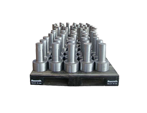
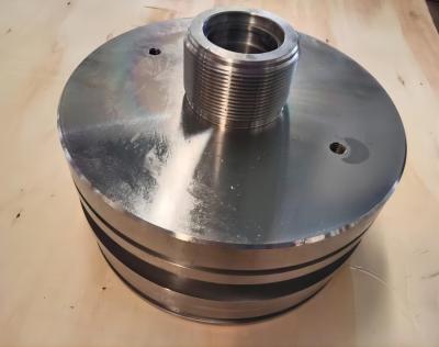
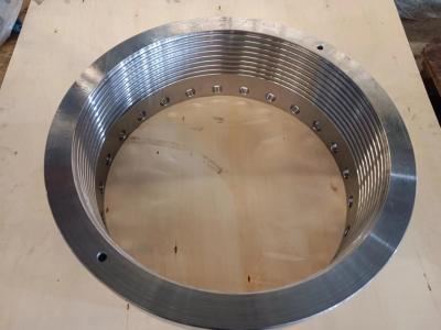
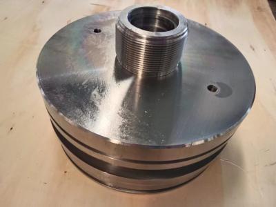
Output Gear Shaft
In design, the application of gear shaft is generally no more than the following:
1. The gear shaft is usually a pinion (a gear with fewer teeth).
2. Generally, the gear shaft is at a high speed level (i.e., at a low torque level).
3. Generally, the gear shaft is rarely used as a sliding gear for variable speed, and is a fixed running gear. First, because they are in a high-speed class, their high-speed is not suitable for gliding and shifting.
4. Gear shaft is a combination of shaft and gear. However, it is necessary to shorten the shaft length as much as possible during design. Too long is not conducive to the upper gear hobbing machine. The support of the shaft is too long, resulting in the shaft becoming thicker and increasing the mechanical strength (such as stiffness, deflection, bending resistance, etc.)
Selection of positioning datum
The machining sequence of the main surface of the gear shaft largely depends on the selection of the positioning datum. The structural characteristics of shaft parts and the position accuracy requirements of the main surface of the spindle determine that taking the axis as the positioning datum is the most ideal. This not only ensures the unity of the datum, but also makes the positioning datum coincide with the design datum. Generally, the outer circle is the coarse datum, and the sharp holes at both ends of the shaft are the fine datum. Pay attention to the following points when selecting.
(1) When the mutual position accuracy between the machined surfaces is required to be high, it is better to finish the machining of each surface in one clamping.
(2) When the top hole at both ends (such as the taper hole of the spindle) cannot be used for rough machining or positioning, in order to improve the rigidity of the process system during workpiece processing, only the cylindrical surface can be used for positioning or the cylindrical surface and the central hole at one end can be used as the positioning reference. During the processing, the outer circle of the shaft and the center hole at one end shall be alternately used as the positioning datum to meet the mutual position accuracy requirements.
(3) If the shaft is a part with a through hole, the original top hole will disappear after drilling through the hole. In order to still use the top hole for positioning, the taper plug with top hole or taper sleeve mandrel is generally used. When the taper of the shaft hole is large (such as the spindle of the milling machine), the taper sleeve mandrel can be used; When the taper of the spindle taper hole is small (such as the CA6140 machine tool spindle), the taper plug can be used. It must be noted that the taper sleeve mandrel and taper plug used should be of high accuracy and their installation time should be minimized. The central hole on the taper plug and taper sleeve mandrel is not only the positioning datum of its own manufacturing, but also the finishing datum of the outer circle of the spindle. Therefore, it is necessary to ensure that the taper surface on the taper plug or taper sleeve mandrel has a high coaxiality with the central hole. For medium and small batch production, the workpiece will not be replaced midway after the taper plug is installed. If it is necessary to repeatedly process the outer circle and taper hole based on the other side, the center hole must be aligned or reground according to the outer circle when reinstalling the taper plug or bushing mandrel.


