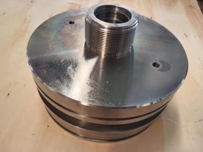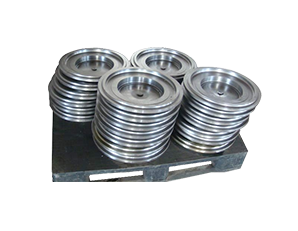
Ring Gear End Cap
The gear end cover includes a circular main body, a number of positioning holes 4 on the main body, and a number of bolt holes 5 on the main body. The positioning holes 4 are located on one virtual circle, and the bolt holes 5 are located on another virtual circle. The two virtual circles are eccentric. For gear end covers of different models, the eccentricity of the above virtual circle is different. The minimum eccentricity is 1.5mm and the maximum eccentricity is 9mm. The virtual circle corresponding to bolt hole 5 is coaxial with the main body.
The purpose of the utility model is to overcome the above shortcomings of the prior art, propose a tooling for gear end caps, which can realize the positioning and fixation of various types of gear end caps.
In order to achieve the above purposes, the utility model adopts the following technical solutions:
The utility model relates to a tool for a gear end cover, which comprises a support plate for supporting the gear end cover; The gear end cover comprises a circular main body, a plurality of positioning holes on the main body, and a plurality of bolt holes on the main body; The positioning hole is located on a virtual circle, the bolt hole is located on another virtual circle, and the centers of the two virtual circles are staggered; The tooling also includes a support beam fixedly connected with the support plate, two locating pegs for threaded connection with the locating holes, two locating slots for locating the locating pegs located on the upper side of the support beam, a number of cushion blocks for supporting the main body, and a connection mechanism for pressing the gear end cap onto the cushion blocks.
Preferably, the cushion block is fixedly connected with the the support plate through bolts.
Preferably, the support plate is provided with a hole at the corresponding position of the cushion block, the cushion block is provided with a second hole, the hole and the second hole are coaxial, the inner diameter of the hole is larger than the inner diameter of the second hole, the hole is provided with a gasket, and the connection mechanism is a fixed bolt used for connecting with the bolt hole thread; The fixing bolt passes through the gasket and the second hole, and the inner diameter of the second hole is larger than the outer diameter of the stud of the fixing bolt.
Preferably, the fixing bolt is m16 hexagonal socket bolt, and the inner diameter of the second hole is 22mm.
Preferably, the gear end cover also comprises an annular bulge on one side of the main body, and the annular bulge is coaxial with the main body; The support beam is inclined, and the positioning groove near the upper end of the support beam is named as the upper positioning groove, and the other positioning groove is named as the lower positioning groove; The upper side of the support beam is fixedly connected with a guide plate, the lower positioning groove is located between the upper positioning groove and the guide plate, the guide plate passes through a guide rod, the guide rod is parallel to the support beam, the side of the guide plate close to the upper positioning groove is provided with a buffer plate, the buffer plate is fixedly connected with the guide rod, the side of the guide plate far from the upper positioning groove is provided with a buffer spring, and one end of the buffer spring is connected with the guide rod, Other end of the buffer spring is connected with the guide plate; A rotation sleeve is rotatably connected with the the positioning pin, and the positioning groove is adapted with the the rotation sleeve; The support plate is provided with a chute, the cushion blocks are connected in the chute in a sliding way, and the support plate is provided with an electric cylinder for driving the cushion blocks; The connecting mechanism comprises a tension bolt for threaded connection with the bolt hole, a slot for inserting the bolt head of the tension bolt at the side of the cushion block close to the main body; The inner diameter of the slot is larger than the outer diameter of the bolt head of the tension bolt; The connecting mechanism also comprises a side sliding groove at one side of the slot, a side sliding block sliding in the side sliding groove, a first cavity and a second cavity sliding in the cushion block, a first piston sliding in the first cavity, a first piston rod for connecting the first piston with the side sliding block, a third cavity sliding in the side sliding block, a third piston sliding in the third cavity, a third piston rod located at the side of the third piston close to the slot A third spring located in the third cavity, an air injection channel for injecting compressed air into the first cavity, a connecting air passage for connecting the first cavity and the third cavity, a guide block slidably connected in the second cavity, a second spring located in the second cavity for resetting the guide block, an intermediate chute between the first cavity and the second cavity, a limit pin slidably connected in the intermediate chute A guide surface at one side of the guide block for driving the movement of the stop pin, an air outlet at one side of the side slider, and an air pipe for connecting the air outlet and the second chamber; The connecting air passage passes through the side walls of the first piston, the first piston rod and the side slider; The limit pin is against the side of the first piston close to the side slider, the limit pin is connected to the guide surface by sliding, the air outlet is located at the end of the side slider close to the slot, the third piston is located between the connecting air passage and the air outlet, and the third piston is provided with a connecting air passage to connect the connecting air passage and the air passage when it moves to the end of the third chamber close to the slot; The lower end of the support plate is rotationally connected with a base, the base is provided with a first motor for rotating the support plate, the side of the support plate close to the support beam is provided with a sliding plate for sliding the main body, the sliding plate is parallel to the support plate, the lower end of the sliding plate is rotationally connected to the base, the base is provided with a second motor for rotating the sliding plate, and the included angle between the sliding plate and the base is 70-80 degrees, One side of the sliding plate close to the support plate is slidably connected with a lifting beam for lifting the main body, and the lifting beam is provided with a lifting cylinder for driving the lifting beam on the sliding plate.